Keeping it simple with SimpleConnect while making Blade Server connectivity as simple as Plug n Play..


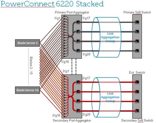
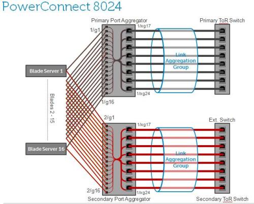
How: By enabling “Simple” mode in Dell PowerConnect Blade Switches, the administrator can simply map internal ports to external ports for traffic aggregation, with feature called “Port Aggregator”.

–        By default, PowerConnect Switches are in “Normal” mode

–        New series of SimpleConnect LAN IO Modules exclusively work in Simple mode.

Providing ability to aggregate traffic from multiple downlinks to a single or fewer uplinks and provide port consolidation at the edge of Blade Chassis.

The Port Aggregator feature minimizes the administration required for managing the Blade-based switches.

Benefits:

  1. Ease of deployment/management for I/O Modules for Blade Server connectivity –Is simple to configure; just map the internal ports to the external ports, assign a VLAN to the group (if required). This feature automatically configures multiple external ports into an LACP trunk group.
  2. Reduce involvement of network admin in blade deployments –Eliminates the need to understand STP, VLANs, & LACP groups.
  3. SimpleConnect is completely interoperable. Full integration of PowerConnect blade switches with 3rd party I/O H/W (Cisco, etc.)
  4. Provides cable aggregation benefit offered by integrated blade switches.
  5. SimpleConnect feature provides loop-free operation without using STP.
  6. It works across a stack of switches (M6220 and M6348) so that you can now manage switches as one via the easy-to-use interface. 

Check out this technology overview video series on Simple Connect LAN modules for M1000e Blade Chassis.

Video1: Shows how simple it is, to deploy blade servers with SimpleConnect, into existing DataCenter LANs.

Video2: This one shows how to deploy blade servers with SimpleConnect, into existing VLANs in customer DataCenters.

Video3: Shows you how easy it is, to manage Blade Server traffic flows with SimpleConnect connecting them to your existing LANs or VLANs in your Data Center.

Technique behind it:

–        The downlink and uplink ports are grouped with a reserved VLAN, so that traffic can only be flooded within that group, and cannot go across.

–        Uplink ports are enabled as members of LAGs (ie: form a Link Aggregation Control Protocol (LACP) trunk group) to connect to uplink switches.

–        Enabling multiple downlink traffic aggregation to fewer uplinks with load balancing capabilities.

Configuring Simple Mode when connecting to Cisco switches

  1. Boot the M6220/M6348/M8024 switch with the default configuration.
  2. Configure four ports (port 1 to port 4) to be a member of a dynamic LAG on the Cisco switch.
  3. Connect a link from port 1 on the Cisco switch to any 1Gig external port on the M6220/M6348/M8024.
  4. Send traffic from both sides. Traffic is switched.
  5. Add another link from port 2 on the Cisco switch to any 1Gig external port present on an M6220/M6348/M8024 switch. The newly added link would automatically be added to the LAG that is being used by the Port Aggregator group and data would be load-balanced.

SimpleConnect Blade Servers with PowerConnect 6220 in Dell M1000e

SimpleConnect Blade Servers with PowerConnect 6348 in Dell M1000e

SimpleConnect Blade Servers with PowerConnect 8024 in Dell M1000e

SimpleConnect provides flexibility to configure multiple port aggregation groups, to meet customer needs to group specific blade servers to manage traffic flows as needed.

SimpleConnect provides flexibility to support traffic flows per customer needs

Also this is designed to simply connect virtualized blade server avoiding complex configuration and management of standard switches.

SimpleConnect simply connecting virtualized Blade servers

Have any of you implemented this in your DataCenters today? Let me know…

Looking in to my DataCenter Crystal Ball…all I could predict about fabric trends for convergence…Do you see it similar???


My Data Center Cystal Ball, What's Your's?


CY2010: Data centers will have either pure iSCSI or FC implementation, from storage point of view

  • 10Gigabit Standard Ethernet adaptation for consolidating 1Gigabit Ethernet infrastructures to support virtualized data centers accelerating data center consolidation.
  • SAN traffic continues to converge on to Standard Ethernet with iSCSI implementations (mostly Greenfield deployments) and 10GE infrastructures. 10GE iSCSI arrays become common in storage deployments furthering iSCSI adaptation.
  • FC networks remain separate, while 10Gigabit Enhanced Ethernet and FCoE is evaluated by early adaptors of these technologies, as products get released in the later in 2010.

CY2011-2014: Data centers will have mixed iSCSI & FC/FCoE.

  • As Enhanced Ethernet standardizes in the middle of 2010, and early standard based products become available by the end of 2010, evaluation of 10GEE starts.
  • During mid 2011, existing FC infrastructures start to merge with early deployments of 10Gigabit Enhanced Ethernet networks with FCoE capabilities promoted by investment protection strategy.
  • At the same time iSCSI deployments leverage benefits of Enhanced Ethernet, furthering it’s adoption. New storage deployments will be either 10G iSCSI or 8G FCoE arrays.
  • This pattern will continue till 40G Enhanced Ethernet products start shipping some time 2012-2013 accelerating the adoption of iSCSI further. 16G FCoE arrays start showing up during that time as an alternative to iSCSI.
  • 40GEE evaluations and early adoptions at the core network throughout 2014 in to 2015.

CY2015 and beyond: Data centers will have converged storage (predominantly iSCSI and to some extent FCoE to attach older storage infrastructure).

  • Converged Enhanced Ethernet networks become mainstream as 40Gigabit Ethernet deployments in the core networks and 10Gigabit Ethernet at the edge becomes common.
  • iSCSI based Storage arrays becomes predominant due to high speeds and performance as compared to FC/FCoE arrays.
  • 100G Enhanced Ethernet!!

 Share your’s…let’s compare 😉

HP’s VirtualConnect technology limitations that I come to know…do you know any more???


  1. Flex-10 NICs work ONLY with VC Flex-10 Switch, to enable FlexNIC functionality. So you cannot use other standard switches, especially Cisco..
  2. Virtual Connect is a L2 Switch supporting proprietary features with limitations, claims compatibility with Cisco networks..but I heard it brought down networks..
  3. Another Management Domain (Virtual Connect Management Domain) is required, with a new set of tools (VCM, VCEM, etc.) and challenges to support Virtual Connect complex infrastructure..
  4. Supported VLAN count is  limited to 128 overall per Virtual Connect Flex-10,  with only 28 per FlexNIC. You got to plan properly in Virtualized enviroments especially due to some of these limitations.
  5. Virtual Connect Flex-10 only allows static allocation of bandwidth per FlexNIC. Changes to a server profile require host reboot. In other words, if you need to reallocate bandwidth (something VMware does on the fly with rate limiting) you must reboot the server.
  6. PXE is only supported on first FlexNIC of a physical Flex-10 NIC port.
  7. Virtual Connect cannot control individual FlexNICs link status, only the link of the physical NIC.
  8. Two FlexNICs from same physical Flex-10 NIC cannot be mapped to same VLAN.
  9. Virtual Connect Flex-10 FlexNICs are not equal in capabilities; they are only logical representations of a physical NIC with reduced & limited functionality. These limitations 4-8 make them behave differently as compared to physical NICs. Especially if fault tolerence is enabled, limitation #6 throws great challenges, if admin could ever figure out how to make it work and understand those limitation!
  10. Smartlink feature does not work for FlexNICs!! Throw more challenges on how NIC teaming behaves and works…
  11. Fibre Channel Virtual Connect needs Ethernet Virtual Connect to function, as VCM is embedded in to Ethernet Module. No too many choices here, you got to go, all in for VC or NOT…
  12. Virtual Connect must be used to get Blade Server Rip & Replace and Provisioning capability. If you use Cisco or ProCurve interconnect HP c-Class cannot support Rip & Replace and Server Provisioning!!
  13. Virtual Connect can introduce duplicate MACs & WWNs on the network, operator could misconfigure a range to overlap. To avoid that VCEM (optional product you need to purchase separately) should used for managing them.
  14. Heard some interoperability issues with SFP+ modules on the Virtual Connect Switch.
  15. Virtual Connect and Virtual Connect Flex-10 cannot work side-by-side in one chassis. So make sure either are same type.
  16. No support for following:
  •  TACACS+/RADIUS AAA service
  •  User configurable QoS features for individual server NICs
  • Port level ACLs & VLAN ACLs
  • Port role with LACP (Virtual Connect decides active/standby).
  • Cannot assign IPv6 Address to VC management interface
  • Ether-Channel/802.3ad/SLB on the downlinks to the server NICs
  •  iSCSI boot & iSCSI Offload
  • Converged Enhanced  Ethernet  (CEE) & Fibre Channel over Ethernet (FCoE)
  •  Single Root – IO Virtualization (SR-IOV)

Let me know if you run in to any other limitations or if they addressed any of these….I think it makes sense to use an enterprise class connectivity device to connect enterprise class Blade Servers…other wise it’s like downgrading your server and network capabilities…Do you want to?? Think hard 🙂

Share your thoughts..

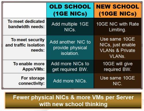
Are you in old school or in new school for virtualization? New trends in Blades…


Virtualization in Old School vs. New School

The practice of using large numbers of GbE connections has persisted even though 10GbE networking provides the ability to consolidate multiple functions onto a single network connection, greatly simplifying the network infrastructure required to support the host. Part of this continuing adherence to a legacy approach is due to the outdated understandings of security and networking. For example, some administrators believe that dedicated VMotion connections must be physically separated because they mistrust VLAN security and question bandwidth allocation requirements. Others assume that discrete network connections are required to avoid interference between network functions.

Virtualization with 1GE NICs for physical isolation and dedicated bandwidth is the old school practice

This topology raises the following issues:

• Complexity and inefficiency: Many physical ports and cables make the environment very complex, and the large number of server adapters consumes a great deal of power.

• Difficult network management: The presence of eight to 12 ports per server makes the environment difficult to manage and maintain, and multiple connections increase the likelihood of mis-configuration.

• Increased risk of failure: The presence of multiple physical devices and cable connections increases the points of potential failure and overall risk.

• Bandwidth limitations: Static bandwidth allocation and physical reconnections are required to add more bandwidth to the GbE network.

The complexity issue and other limitations associated with GbE described above can be addressed by consolidating all types of traffic onto 10GbE connections. With the advent of dynamic server consolidation and increasingly powerful servers, more workloads and applications than ever before are being consolidated per physical host. As a result, the need is even greater for high bandwidth 10GbE solutions. Moreover, features that provides high performance with multicore servers, optimizations for Virtualization, and unified networking with Fibre Channel over Ethernet (FCoE) and iSCSI make 10GbE the clear connectivity medium of choice for the data center. Moving from multiple GbE to fewer 10GbE connections will enable a flexible, dynamic, and scalable network infrastructure that reduces complexity and management overhead, and provides high availability and redundancy.

The obvious advantage of the 10GbE solution is that it reduces the overall physical connection count, simplifying infrastructure management considerations and the cable plant. Moving to a smaller number of physical ports reduces the wiring complexity and the risk of driver incompatibility, which can help to enhance reliability. For additional reliability, customers may choose to use ports on separate physical server adapters. The new topology has the following characteristics:

• Two 10GbE ports for network traffic, using NIC teaming for aggregation or redundancy

• One to two GbE ports for a dedicated service console connection on a standard virtual switch (optional)

• SAN converged on 10GbE, using iSCSI

• Bandwidth allocation controlled by VMware ESX

This approach increases operational agility and flexibility by allowing the bandwidth to the host and its associated VMs to be monitored and dynamically allocated as needed. In addition to reducing the number of GbE connections, the move from a dedicated host bus adapter to Ethernet Server Adapters with support for iSCSI and FCoE can take advantage of 10GbE connections.

Placing the service console network separate from the vDS can help avoid a race condition and provides additional levels of redundancy and security.

Virtualization with 1GE and 10GE NICs as trasition from old school practice to new school

Using VMware Virtual Distributed Switches vDS features manages traffic within the virtual network, providing robust functionality that simplifies the establishment of VLANs for the functional separation of network traffic. This virtual switch capability represents a substantial step forward from predecessor technologies, providing the following significant benefits to administrators:

• Robust central management removes the need to touch every physical host for many configuration tasks, reducing the chance of mis-configuration and improving the efficiency of administration.

• Bandwidth aggregation enables administrators to combine throughput from multiple physical server adapters into a single virtual connection

• Network failover allows one physical server adapter to provide redundancy for another while dramatically reducing the number of physical switch ports required.

• Network VMotion allows the tracking of the VM’s networking state (for example, counters and port statistics) as the VM moves from host to host.

• Port groups provide the means to apply configuration policies to multiple virtual switch ports as a group. For example, a bi-directional traffic-shaping policy in a vDS can be applied to this logical grouping of virtual ports with a single action by the administrator.

• VLANs allows network traffic to be segmented without dedicating physical ports to each segment, reducing the number of physical ports needed to isolate traffic types.

• Failover can be achieved with two physical 10GbE ports by placing administrative, live migration, and other back-end traffic onto one physical connection and VM traffic onto the other. To provide redundancy between the two links, configure the network so that the traffic from each link fails over to the other if a link path failure with a NIC, cable, or switch occurs.

Virtualization with all 10Gig NICs and VLANs is the new school practice addressing NIC proliferation and bandwidth needs

Enabling VLAN tagging and QoS capabilities of 10GE NICs plus advanced capabilities of VMware Distributed Virtual Switch (vDS) (such as Bi-directional Traffic Shaping using Rate Limiting, Port Grouping, VLAN Tagging, and Private VLANs), we can get required traffic isolation and dedicated scalable bandwidth needed for virtualization.

This makes good sense especially in Blades where 1G NIC sprawl issue can be effectively countered and  virtualization can be furthered as 10G provides the fat pipe needed to run lot more VMs per physical server.

I believe it’s time to move to new school practices….taking full advantage of exciting technologies like multicore CPUs, 10GE fat pipe, Fabric convergence, Distributed Virtual Switches, etc….Don’t you ???

Why Flex-10? Do you know!!


Looking for a good reason why Flex-10 is even needed!!

 The capability to divide 10G in to four FlexNICs is presented by HP as the solution needed for virtualization to meet traffic isolation and dedicated BW requirements. Instead of using multiple 1Gig NICs they suggest use a 10Gig Flex-10 NIC and slice it in to 4 FlexNICs. Then use these partitioned FlexNICs for meeting dedicated BW requirements per traffic type.

I thought to myself, why I should partition the 10Gig pipe for isolation and dedicated bandwidth. Instead why don’t I use VLANs for isolation and Rate limiting to shape traffic.

So I don’t think Flex-10 has any value proposition here.  On the other hand, it just adds more complexity to standard 10Gig NIC…

My other issue is this FlexNIC capability can only be leveraged with VC modules, since both have Broadcom chips that are compatible to enable this function and it doesn’t work with any other HP blade switch or to that matter any other top of the rack switch. This issue is now tying me down to VC only option, running me into all limitations of VC technology. So instead of value add here, I am actually downgrading my network capabilities if I end up with VC.

I ran in to all those blogs out there, thinking that I didn’t know something that they know about Flex-10 and VC, and that is why they are for it. Now I am a little disappointed that I did not find those value propositions that this technology is bringing to virtualization, than those other technologies already did. A value proposition may drive my decision to adapt Flex-10 VC, but what is it??

So, till then I strongly believe it is better to have normal 10G NIC in the server and connect to standard L2 switch, enable vDS existing features such as Rate limiting, Port Groups, VLAN tagging….this way you get all the consolidation (of Servers, of NICs, of Switches, etc) using virtualization and get overall Data Center consolidation without locking down further proprietary solutions….This way I am ready to take advantage of future IO and Fabric Consolidation as standards ratify early next year or so…and not worry about interoperability issues in my Data Center..

I would be glad to hear more about the really Value Proposition of Flex10 VC…

Anyone??  Please share…

Sri

Talking about "Pinning the wrong way" – another smart UCS idea!!


This totally surprised me as I understood it right, looks like Cisco got it wrong big time with this “pinning” feature in UCS IO Module FEX!!! They have fixed configurations for traffic flow from server slots depending on how many uplinks are used. So if you ever change the number of connected uplinks, then you need to relocate servers to appropriate slots based on bandwidth requirements, following the pinning table below.

That’s totally not a really smart idea!

Read this from UCS configuration guide:

Pinning Server Traffic to Server Ports

All server traffic travels through the I/O module to server ports on the fabric interconnect. The number of links for which the chassis is configured determines how this traffic is pinned.

The pinning determines which server traffic goes to which server port on the fabric interconnect. This pinning is fixed. You cannot modify it.

As a result, you must consider the server location when you determine the appropriate allocation of bandwidth for a chassis.

You must review the allocation of ports to links before you allocate servers to slots. The cabled ports are

not necessarily port 1 and port 2 on the I/O module.

If you change the number of links between the fabric interconnect and the I/O module, you must reacknowledge the chassis to have the traffic rerouted.

Note

All port numbers refer to the fabric interconnect-side ports on the I/O module.

Chassis with One I/O Module (FEX)

So you can have two servers per uplink leading to 2:1 subscription if all the four links are used, but the traffic flows are fixed. For example, traffic from Server 1 and 5 share uplink1. You don’t have a choice to change that, remember pinning is fixed and you cannot modify, but your choice is to decide if  two servers A and B has higher bandwidth requirements, then you don’t want them in Slot 1&5 or 2&6 or 3&7 or 4&8 together, to avoid bandwidth starvation. So you may want to plug Server A with Server C because server C needs little bandwidth. If all the servers need higher bandwidth, then all of them will starve now and then…..

What happens if your uplink bandwidth needs change?

For example, let say you had 2 uplinks connected and you made sure servers are plug in to appropriate slots such that none of them starve for uplink bandwidth. Finally you optimized that.

Then later you decided that you connect more uplinks to support your new bandwidth needs, let’s say 4. Since the server slots pinned to a specific uplink changes as you connected 4 uplinks, you have to figure out again which slot specific server should go so that they don’t compete for uplink bandwidth and avoid starvation. 

I think Cisco “Pinned” themselves wrong with UCS!! Don’t you??

Cheers

Sri

HP stole my song……………so, why am I not pissed?


I have been singing this song for couple of year….and to my surprise HP now singing mine….

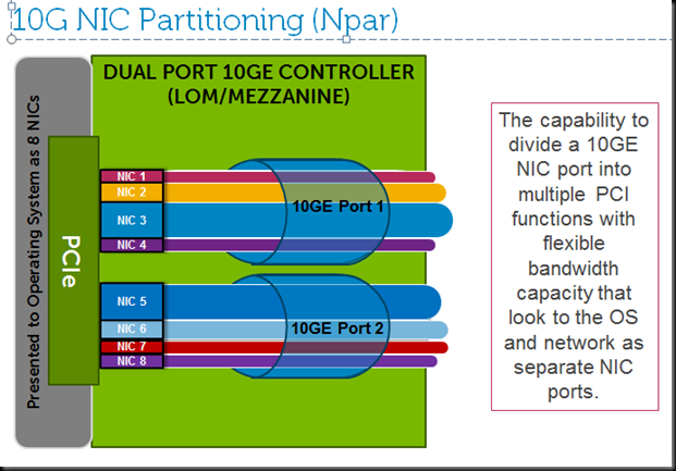
Enhancing Scalability Through Network Interface Card Partitioning (Npar), while being switch agnostic….I think it is better that way…will you agree?


Switch agnostic portion, which is fundamentally a big differentiation….as you have a option of choosing your choice of switching infra…that could be open and affordable.

The Bandwidth on the wire is efficiently used, means all the bw available is used at any time needed. For example, if a NIC partition is assigned certain bw say 2G and if that partition needs more that 2G at certain time when it ends up with burst traffic such as vMotion, the dynamic bw feature will allow it to use more than the limit if the all 10G bw on the wire is not fully utilized by other partitions. This is efficient way of using all the bw available on the wire vs HP assigns BW per flexNIC and it will not share with any other partition even if needs it…that means very static partitioning…minimizing effective use of all the wire speed when needed. Admin as to fine tune configuration per need….which could change day to day. Huge differentiation for our NPAR.

Npar provides makes things economical….as it replaces multiple adaptors including storage and Ethernet if it supports FCoE and iSCSI. Now you can partition one to do Storage function with appropriate bw like 5G or 6G as needed.

Npar supports capability to have Jumbo frames on one partition while other partitions use normal frame size….this eliminates the need to have a separate adaptor. That is a unique differentiation which lets customer to have only one adaptor for iSCSI storage with Jumbo frames enabled and normal LAN traffic on the same wire. Less adaptors, cables, and switches….

NPAR is OS agnostic, since it is enabled at bootup it is presented to OS as though they are normal physical NICs…so OS don’t have to change any behavior. So working with all the standard and advanced functions adaptors support today. Very much deployable in to existing infrastructures bringing these new technological and economic advantages in to existing data center.

NPAR can address NIC/adaptor sprawl, while making it easy to transition to 10G, even your application fully don’t need all the 10G bw. It brings you with speeds that are in between 1-10G to fine tune to your app needs…

image

To summarize the Dell Npar differentiation:

  • Switch agnostic implementation
  • Dynamic BW use and flexible bw size allocation
  • Make things more economical- less adaptors, less switch ports, less cables!!
  • Supports Jumbo frames for iSCSI
  • OS agnostic
  • Solution to NIC sprawl

Let me know your thoughts…

Cheers

Sri

Alien

Talking about "Pinning the wrong way" – another smart UCS idea!!


This totally surprised me as I understood it right, looks like Cisco got it wrong big time with this “pinning” feature in UCS IO Module FEX!!! They have fixed configurations for traffic flow from server slots depending on how many uplinks are used. So if you ever change the number of connected uplinks, then you need to relocate servers to appropriate slots based on bandwidth requirements, following the pinning table below.

That’s totally not a really smart idea!

Read this from UCS configuration guide:

Pinning Server Traffic to Server Ports

All server traffic travels through the I/O module to server ports on the fabric interconnect. The number of links for which the chassis is configured determines how this traffic is pinned.

The pinning determines which server traffic goes to which server port on the fabric interconnect. This pinning is fixed. You cannot modify it.

As a result, you must consider the server location when you determine the appropriate allocation of bandwidth for a chassis.

You must review the allocation of ports to links before you allocate servers to slots. The cabled ports are

not necessarily port 1 and port 2 on the I/O module.

If you change the number of links between the fabric interconnect and the I/O module, you must reacknowledge the chassis to have the traffic rerouted.

Note

All port numbers refer to the fabric interconnect-side ports on the I/O module.

Chassis with One I/O Module (FEX)

So you can have two servers per uplink leading to 2:1 subscription if all the four links are used, but the traffic flows are fixed. For example, traffic from Server 1 and 5 share uplink1. You don’t have a choice to change that, remember pinning is fixed and you cannot modify, but your choice is to decide if  two servers A and B has higher bandwidth requirements, then you don’t want them in Slot 1&5 or 2&6 or 3&7 or 4&8 together, to avoid bandwidth starvation. So you may want to plug Server A with Server C because server C needs little bandwidth. If all the servers need higher bandwidth, then all of them will starve now and then…..

What happens if your uplink bandwidth needs change?

For example, let say you had 2 uplinks connected and you made sure servers are plug in to appropriate slots such that none of them starve for uplink bandwidth. Finally you optimized that.

Then later you decided that you connect more uplinks to support your new bandwidth needs, let’s say 4. Since the server slots pinned to a specific uplink changes as you connected 4 uplinks, you have to figure out again which slot specific server should go so that they don’t compete for uplink bandwidth and avoid starvation. 

I think Cisco “Pinned” themselves wrong with UCS!! Don’t you??

Cheers

Sri

Smile

“Power to do more”….another catchy phrase or for real…


Recently I ran in to the post my good friend John Barnhart at Dell wrote. I thought of sharing it with my friends here as it talks about how Dell PowerEdge Blades are packed with punch, to enable you to do more…

Here is John’s post:

“The slogan “The Power to do More” has never been more appropriate when discussing Dell’s latest PowerEdge 2 Socket servers combined with the latest 4 and 6 core Intel Xeon 5600 Westmere-EP processors.

On February 14, 2011 Dell announced a very significant update to the entire lineup of two-socket PowerEdge servers, including the M610, M710, M610X and M710HD blades, R710, R610, R510, R410, C1100, C2100, C6100 rack servers, and T710, T610, T410 towers with new Intel Xeon 5600 series Westmere-EP processors.

It is reasonable to assume that a great deal of attention was directed at Dell by the tech world considering the extensive depth of the refresh, especially when it offered the latest Intel 4 and 6 core processors at previous dual core price points. Yes, that is right, up to six cores at previous price parity.

However, one day after the Westmere-EP announcement Dell released financial results that were so far above financial analysts expectation that the buzz throughout the world about Dell’s financial success overshadowed what may just be one of the most significant processor upgrades in Dell’s product line since the release of Dell 11th Generation Power Edge servers in 2009.

Dell Power Edge Blade, Rack and Tower servers are widely popular with a variety of customers for their ease of management, virtually tool less serviceability, power and thermal efficiency and customer inspired designs, but when it comes to performance they have once again leap-frogged the competition by offering significant gains in performance with the latest Intel Xeon 5600 series refresh.

As an example, testing conducted by Dell’s internal laboratories using a 1U 2Socket R610 rack server equipped with the new X5687, 3.60 GHz Intel Xeon processor, delivered previously unachieved performance benchmarks above any other competitors 8, 12, and 32 core product in both SPECint_rate2006 and SPECfp_base2006 as detailed on http://www.spec.org. When reviewing the benchmark list the competitors which Dell testing results blew past is extensive and includes products from IBM, Fujitsu, Hitachi, NEC, and Oracle/Sun, just to name a few.

Dell’s use of the Intel Xeon 5600 Westmere-EP processor to refresh its lineup of two socket servers offers customers the opportunity to realize outstanding integer-computing throughput and floating-point computation performance at a level previously not available on Dell Power Edge 2 socket blade, rack and tower servers.

Get past the technical buzzwords and what it means to Power Edge customers in real-terms is that they can expect to see improved performance as they share, access and update the most commonly used files across their network including word documents, spreadsheets, graphics presentations, 3D applications as well as various other financial, analytical and highly algorithm dependent data shares.

Every newly released Intel 5600 processor regardless of where it appears in the stack, offers AES-NI and TXT technology specifically designed to reduce malware risks so virtualized mission critical applications are more secure making previously dedicated servers available for upgrades, repurposing, or replaced as business needs change.

For those waiting to perform a refresh so they could dive deeply into the virtualization era or IT managers struggling to keep their servers online with duct tape, bubble gum and a prayer, the time has never been better to upgrade to Dell Power Edge 2 socket servers with the latest Intel Xeon 5600 series processors. To find out how you and your organization can get “the Power to do More” click http://www.dell.com/poweredge”

He shed light on various aspects of these servers and why he thinks these Dell Blades are best enabled to let to with the power to do more….I agree with him.

What do you think? Glad to hear from you…

Cheers

Sri

Do you see a need to manage bandwidth for avoiding traffic contention on 10Gigabit Super Highway in virtualized Datacenters? Here is my take on it…what’s yours?


First of all, 10Gig is a huge jump in the amount the bandwidth made available for use for server connectivity, as compared to today’s 1GE options…Remember we were running our business today with about 8 or 12  1GE NICs and couple of 4G HBAs for network and storage connectivity in the server. Two of these 10Gig NICs can bring 20Gig to play with, for similar purposes, which infact is equal or more than we are used to today. If we need more in future, we could always add few more 10Gig NICs to share the traffic loads of tomorrow.

Since the bandwidth is a constraint in 1Gig world as today’s applications grew out of those bandwidths available, we needed to manage traffic congestion, and all these technologies that talk about dedicated bandwidth per traffic type made much sense…

But when you move on to 10GE connectivity…That is a different story!!…Since you got more bandwidth than you need for today’s traffics and while that guarantees congestion free traffic flows; traffic management tools like NIC partitioning techniques like HP Flex-10, VMware Rate Limiting, Network IO control (NetIOC)….are not needed at all.

At this point, all these bandwidth management schemes are unnecessary and should not be used to avoid the complexities that they bring along with feature functions they support..

10GE brings much needed port consolidation (especially in compact form factors like blades) and also a bandwidth capacity that is more than you need for today’s applications and traffics..

We have to make that point clear to the technology consumers and shift them from old school thinking of dedicated physical ports with specific bandwidths, etc…for meeting traffic isolation and bandwidth needs; to new school thinking of sharing the same wire and using VLANs and other techniques.

To sell their stuff…what some companies (selling proprietary techniques like Flex-10) are doing is, fanning the existing paranoia or fear of critical traffic not having enough bandwidth on the wire…while not highlighting that 10Gig actually solves bandwidths needs by itself, on it’s own, & no need for special techniques, period!!

If your core infrastructure is not ready for 10Gig connectivity, then you should look for high port density solutions like Dell 1GE Quad Port NICs with PowerConnect M6348 high port density Switches for M1000e Blade Chassis…to serve the need to have more ports to support virtualization.

Right industry standard technologies are evolving to support the need to improve efficiency in IO virtualization like Single Root IO Virtualization (SR-IOV)…which is much needed, to bring the benefits of Virtualization to every type of computing including HPC.

SR-IOV is not about carving bandwidth, in fact it does not do that at all. It virtualizes a physical NIC and presents as multiple devices to hypervisor…hypervisor does that today. So SR-IOV technique is offloading that work to a NIC and leaving more cycles for hypervisor to do important things like supporting more VMs 🙂 and running them more efficiently. Also it supports direct access to these devices from guest VMs/OSs, bypassing hypervisor…drastically improving efficiency while still able to do vMotion as hypervisor still have access to control plane of these devices. All these devices share the same wire…so there is no dedicated bandwidth per device here…remember 10Gig is enough!!

When in future, if Users run into bandwidth contention, even with 10Gig NICs because apps grew out and started generating larger traffics, then they can add more, like they do today with 1Gig NICs…

In a “worst case”, where they still run in to bandwidth contention as they ran out of space to add more 10NICs, then we still have better tools like NetIOC or Rate Limiting for traffic shapping….and I don’t see that need in the near future.

Hope this makes sense…and provides the bigger picture on 10GE for Virtualization..

Let’s get it right, the correct perception of using these 10GE super highways…where you don’t need traffic management, when there is no congestion….in my words “simply don’t add complexity when not needed”. 

In the mean time, we are working hard to make those technologies that are much needed like SR-IOV, happen in real products…as it makes better sense.

That’s my take on this topic…what’s yours?

Here are few papers out there which dwells deep on this subject,

  1. Simplify VMware vSphere* 4 Networking with10 Gigabit Server Adapters

  2. “Optimizing QoS for 10GE in Virtual Networks”


  3. Virtual Switches Demand Rethinking Connectivity for Servers

    Signing off for now…..Sri

One, two, three….Done! Now UCS added to your Data Center! Cisco’s cool-aid or is it true?


I recently had an interesting conversation with Brad Hedlund, Data Center Solutions Architect at Cisco Systems who passionately promotes UCS through his blogs.

During the conversation regarding UCS scalability and bandwidth management, he mentioned about how easy it is to get UCS chassis added to data center. I thought I share that conversation. So read on….what Brad said and then what I said….

——————————————————————————————————————————-

Here’s how many steps it takes to get a Cisco UCS chassis added to the data center:

1) Connect the power cables

2) Connect the Ethernet cables

3) Acknowledge the chassis in UCSM

–DONE–

 How many configuration steps are required to add a Dell chassis to the data center? That’s my challenge to you.

 Cheers,

Brad

——————————————————————————————————————————-

Keep reading…

——————————————————————————————————————————-

Brad,

Another big claim from Cisco and now you, is how easy it is to get UCS added to data center!! How easy it is to get those computing nodes working in three steps…and help customer business just like that 🙂 I wish it is true…

 For a second, I will take your word on it. I will complete those three steps like you said and say DONE! Do you think, now I got my Cisco servers running and handling my business?

 In fact, I know I will end up with just more HW powered up and do nothing but creating electric bills 🙂 You failed me Brad!

 Now don’t tell me, I have to do more. Like before I do those 3 steps, I have to have or if I don’t, then setup the infrastructure to deploy servers (let’s start with image deployment, application deployment, Virtualizing servers etc…).

 I don’t think UCS does all that, it needs third party tools. So, I have to make sure all those tools which I use are integrated in to this new UCS Manager API. (That definitely needs a lot more steps not just three!!)

 If only 3 steps like you said are needed, Cisco don’t need to create new company ‘Acadia’ with the help of partners to provide services to help customers with setting this UCS system in data center. So they know it is complex enough so customers will be willing to pay for it. Cisco sees this as another business, so they started a venture capital to sell Vblocks…

 In fact, Cisco just delivers pieces of HW with an optimized device manager to manage them, taking advantage of still evolving technologies such as DCB, FCoE, SR-IOV…etc, based upon pre-standard proposals/drafts or proprietary ones, remember VN-Tag…

 I don’t think Server Customers are that naive, to believe that Cisco came up with this revolutionary platform that will auto magically in three steps make their data centers as a dynamic IT infrastructure. Years of providing server technologies by companies like Dell, provided some deeper understanding of what it takes to deliver an optimized data center to support business needs, I don’t think Cisco lack’s that…wait a minute! Or Does it? So, why are they asking customers to ‘Nuke & Pave’ their existing environments  and go with new architecture with UCS, in order to get those efficiencies. Definitely they know networking side of the business needs and services, but are we sure if Cisco knows about Server side of it…

In my humble opinion, I think Cisco failed to push Nexus into data centers from last 3 years, (as customers are not in favor of adapting Nexus OS with subset of  features as compared to Catalyst IOS). So back to selling vision game plan and they are selling this as new vision ‘Unified Computing System’, to sell more Nexus gear. Didn’t Cisco do some things like this before; remember Unified Communications vision to sell more Catalyst gear….

So, selling another vision!! Great new vision or just a polished version of original data center vision, server and virtualization vendors had 5 years back? Kudos to Cisco marketing…for painting that rosy picture :). I agree they really brew good cool-aid..

 I am sure you will not moderate my response and will post this one as is! And dissect it with all honesty. 

Yes with all honesty Dell Chassis needs more steps and does lot more! By the way, you know, we tell customers that there is no need to ‘Nuke & Pave’ their environments, in order to get those new data center efficiencies. Just leverage all those technologies you trusted your business with all these years, while embracing newer complimentary technologies like 10GE, Converged Enhanced Ethernet (per DCB), FCoE, iSCSI, and IO Virtualization, to name a few..

 Cheers again!

Sri

——————————————————————————————————————————-

Wondering how many really think this new flavor of old Data Center cool-aid which Cisco selling aggressively is different and revolutionary from what we envisioned, even before Cisco learned, “What is a server?” ….

Please share your thoughts…

HP throws “Tolly” at UCS Bandwidth and Scalability, Cisco counters with “Folly”..so let’s deep dive to find ourself “Truly” :)


Hope you ran in to these links before….one is Tolly and other is Folly…..So I started looking for Truly…..and found this…IS IT TRULY?? You tell me after reading my stolly…(sorry i tried to rhyme :))

HP sponsored Tolly report saying UCS bandwidth sucks as compared to HP BladeSystem…

http://www.tolly.com/Docdetail.aspx?Docnumber=210109

Brad Hedlund, Data Center Solutions Architect at Cisco Systems, calling it Folly:

http://www.internetworkexpert.org/2010/03/02/the-folly-in-hp-vs-ucs-tolly/comment-page-1/#comment-789

Tolly’s paper, it actually exposes bandwidth bottle necks with FEX “pinning” feature and it’s diminishing effect on UCS scalability. 

Here is my analysis on it:
This surprised me as I understood it! As I understood this “pinning” feature of UCS Fabric Extender (IO Module)!!! It has fixed configurations depending on how many uplinks are used to connect FEX to 6100 FI.

From UCS Manager GUI config guide:
Pinning Server Traffic to Server Ports
All server traffic travels through the I/O module to server ports on the fabric interconnect. The number of links for which the chassis is configured determines how this traffic is pinned.

The pinning determines which server traffic goes to which server port on the fabric interconnect. This pinning is fixed. You cannot modify it. As a result, you must consider the server location when you determine the appropriate allocation of bandwidth for a chassis.

You must review the allocation of ports to links before you allocate servers to slots. The cabled ports are not necessarily port 1 and port 2 on the I/O module. If you change the number of links between the fabric interconnect and the I/O module, you must reacknowledge the chassis to have the traffic rerouted.

For example: if you use 2 uplinks today and tomorrow you decide to use 2 more, then to optimize bw use of servers, you got to physically shuffle servers, so that two busy server don’t pair up. In a virtualized evironment this means atleast move VMs around right physical server pair for proper bw optimization!! Otherwise they may have to fight for BW 🙂

So you can have two servers per uplink leading to 2:1 subscription if all the four links are used, but the traffic flow are fixed.

For example: Traffic from Server 1 and 5 share uplink1. You don’t have a choice to change that, but your choice is if server A and B has higher bw requirements, then you don’t want them in Slot 1&5 or 2&6 or 3&7 or 4&8 together, to avoid BW starvation. So you may want to plug Server A with Server C because server C needs little bw.

This paper exposes this fundamental design problem and highlights it as limited BW aggregation capability. In the enthusiasm of doing that, they forgot that Cisco uses two FEX modules and both can be active at the same time. So effectively aggregate uplink bw will be 9.1 x 2 = 18.2 Gbps per two servers if all uplinks are used.

So from server pair point of view, if it has 2×10gig CNAs, then 40gig downlink traffic should share 20Gig uplink bw. Means 2:1 oversubcription….

If scaled to 320 servers as Cisco UCS claims, then the oversubscription will be 8:1, in other words, if customer has apps running on these blades that need high bw, then scalability story runs short quickly..

I have posted a comment on Brad’s blog to his response to Tolly with his Folly, I wonder if he is going to publish it and is up to my challege to explain the bandwidth and scalability story truly….

So this is my TRULY for that TOLLY and FOLLY….

What is yours?

Is 10Gig just an Ethernet speed bump? Fat Pipe? Or what else!!


It’s just an Ethernet Speed Bump to alleviate the 1Gigabit NIC sprawl in virtualized environments and to promote data center consolidation. 10Gigabit Standard Ethernet goes through Phase 1 adaption providing the big fat pipe, while storage traffic consolidation on to it with proven technologies like iSCSI is on going side by side.

Now it’s more than that! …

Phase 2 adoption of 10GE is with Enhancements to Ethernet to support FC traffic, leveraging widely implemented FC storage infrastructures in data centers. Since new technologies are added and being evaluated, this phase 2 adoption needs to go thru maturity period. These new convergence technologies CEE/DCB (Converged Enhanced Ethernet based of Data Center Bridging IEEE standards) and FCoE (Fibre Channel over Ethernet) get implemented in the Server/Network edge first, then Core of the network, and later at Storage End with FCoE Arrays etc… 

‒      Provides Single Fabric: Reduces management and deployment costs, as Fabric of Choice

‒      Optimized for virtualization: More VMs means more server and network traffic so an efficient network is required. Multi-core processor-based platforms handle larger workloads so need  faster network throughput to reduce latency to storage devices

 ‒      Drives storage over Ethernet: Consolidate LAN and SAN (w/ FCoE) FC infrastructure/traffic on a single 10Gig Enhanced Ethernet based of DCB standards, with full traffic isolation & robust Quality of Service with Congestion Management.

Single wire with 10GE

10GE Turbo-Boosts Infrastructure Consolidation in Data Center

–      Reduces the number of cables and server adapters

–      Lowers capital expenditures and administrative costs

–      Single fabric type simplifies setup and VM migration  

–      Reduces server power and cooling costs

–      Blade Servers and Virtualization drive consolidated bandwidth

So much going on with 10Gig Ethernet, as we see the hockey stick happening with it’s adoption…2010 for 10Gig…coincidence… not really…it’s just happening!!

10GE Adaption

It may take few years for complete infrastructure to upgrade to 10GE technology – ALL 10Gig !! 

Cost of 10GE still needs to come down for further adaption, while performance & throughput of 10GE technology has some challenges in virtualized environments inhibiting further adoption at server level…Should we still wait??

I would say, it’s time to adapt:

10GE, it just works!

What do you think it is? Share your thoughts…